Operand Forwarding Networks
CS 641 Lecture, Dr. Lawlor
This is an interesting paper comparing several radically different ways of moving data around a single chip:
M. Taylor, W. Lee, S. Amarasinghe, A. Agarwal, "Scalar Operand Networks", IEEE Transactions on Parallel and Distributed Systems, vol. 16, no. 2, Feb 2005.
One thing I really like about this paper is the notion that
superscalar, multicore, and distributed networks are all just different
approaches for shuffling data between arithmetic units.
Multiplexors and Busses
There are many places on a CPU where you need to choose one output of several possible inputs:
- The result of each operation can be driven by any arithmetic unit.
- Each output from the register file can be driven by any register.
The typical way to do this is using a multiplexer, or "mux", typically implemented using logic gates.
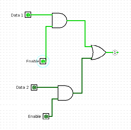
But there's another implementation using an analog circuit trick: you
can tie together several output lines, as long as you only enable a
single output line at a time. The big difference is that an
output device can enter a high-impedance "disconnected" state, leaving
to three modes: "on, off, or don't care", hence called tri-state logic.
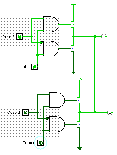
These can be further simplified by noticing that the AND gates are only needed if the enable is true:
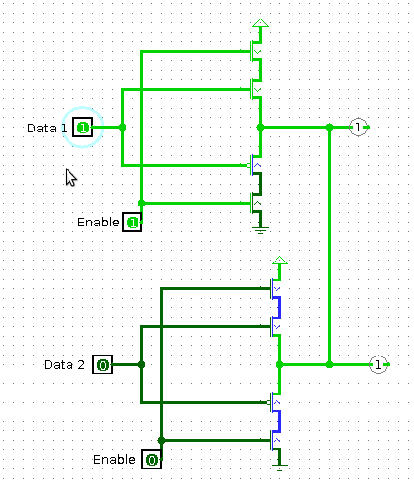
This tri-state solution only uses four transistors per output bit,
which is substantially fewer transistors than the mux approach (at
least 4 transistors per AND gate, plus the OR gate), and hence the
tri-state output bus solution is standard.
If you look at the 8008 microarchitecture, there's one big data bus running around the entire CPU.
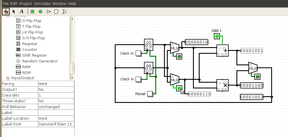
Simple CPU Design
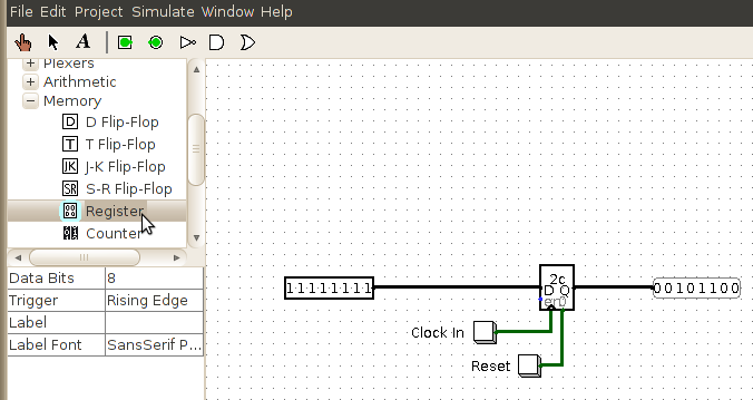
Here's a basic Register, which stores a value (displayed inside),
always outputs the value on the Q output, clears the value to zero with
the "0" input (bottom right side), and reads a new value from D when
you bring the "en" clock input high. I'm using an
"Input->Button" as a momentary input to clock in values, or reset
the value to zero. Click the image to get a Logisim .circ file to
play with.
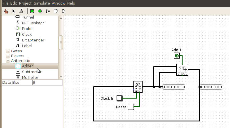
Here's the same register's output fed into an adder, which is then fed
back into the register's input again. This circuit just doubles
the value every time you hit "clock in".
Of course, a real CPU has lots of operations, not just addition.
But we can support different operations by multiplexing which operation
we want, using a "Plexers -> Multiplexer" or "mux". The mux's
input determines which operation we perform.
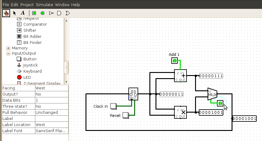
Finally, a real CPU can store more than one value at once. We can
choose which register to use as an input, by using a mux the same
way. We can now poke the various buttons, and get addition or
multiplication on any of the stored register values, store the value
back to any register, and operate back and forth indefinitely.
Given a list of button values, this circuit can compute stuff.
It's a CPU!