In 1996 Spring Proceedings (Cray User Group), pages 155-159, 1996.
Volume Rendering of Large Datasets on the Cray T3D
Greg Johnson
Arctic Region Supercomputing Center
University of Alaska
Fairbanks, AK 99775-6020
Jon Genetti
Department of Mathematical Sciences
University of Alaska
Fairbanks, AK 99775-6660
Abstract
We have produced a memory optimized volume renderer called Splatter
for the Cray T3D.
Splatter can render the 512x512x1877 CT dataset (1 GB) from the
Visible Human Project in 6.14 seconds on 128 PEs and 11.64 seconds on
64 PEs.
Splatter can also render a 1024x608x1877 version of the cryosection
dataset from the Visible Human Project in 11.8 seconds on 128 PEs and
23 seconds on 64 PEs.
An AVS interface gives the user control of the resolution of the
shaded data, so large datasets are more likely to fit in memory.
1 Introduction
Direct volume rendering of medical data involves taking a set of raw
data slices, processing them in some way (shading), and extracting a view.
There are many ways to extract a view from shaded slices and Splatter
currently uses splatting [6]
(see [2] for an analysis of the ray casting and splatting
algorithms on the Cray T3D).
The volume is projected voxel-by-voxel onto the raster in a
front-to-back traversal.
With a parallel projection, the footprint (or projection) of a voxel on
the raster is constant for all voxels.
Since a voxel rarely projects onto a pixel exactly, a filter spreads
out the color and transparency to neighboring pixels.
When creating multiple images from different viewpoints, the volume
must be re-shaded prior to extracting a new view, unless the position
of the light source relative to the volume is fixed.
In Splatter, the light source moves with the volume but
the user can also move the light source independent of the viewing
position.
2 Visible Human Project
The National Library of Medicine has provided several large, high
resolution medical volume datasets through the Visible Human
Project (VHP).
These datasets will be referred to CTmale, CTfemale, RGBmale and
RGBfemale in this paper.
CTmale is an axial CT scan of a frozen male cadaver taken at 1 mm
intervals that contains 1877 slices at 512x512 x 2 byte resolution
(930 MB).
CTfemale is an axial CT scan of a fresh female cadaver taken at 1 mm
intervals that contains 1734 slices at 512x512 x 2 byte resolution
(890 MB).
A novel part of the VHP is the generation of cryosection slices
by taking digital color images of the cadaver while removing 1 mm (for
the male) or 1/3 mm (for the female) after each image.
An example from the female head is shown in Figure 1.

Figure 1: A cryosection slice.
The male dataset contains 1878 slices of RGB data at 2048x1216 x 3 byte
resolution (13 GB).
The female dataset contains 5189 slices of RGB data at 2048x1216 x 3 byte
resolution (37 GB).
By cropping the images to the smallest rectangle of real data, the male
dataset can be reduced to 4.8 GB and the female dataset to 9.6 GB.
RGBmale is a half-resolution (1024x608) version that requires 1.6 GB for
the shaded slices (1.2 GB + 0.4 GB for the alpha values).
RGBfemale is a half-resolution (1024x608) version that requires 3.2 GB
for the shaded slices (2.4 GB + 0.8 GB for the alpha values).
3 Cray T3D Architecture
The Cray T3D system is a massively parallel superscalar multiprocessor
architecture.
The processing elements (PEs) are Digital Equipment Corporation's 150 MHz
Alpha micro-processor model EV-4 and are paired off into nodes.
Inter-node communication occurs via the T3D's high performance interconnect
network which has a 3D toroidal topology.
Each node contains one network switch with a peak transfer rate of 300MB
in each of six directions (bidirectional in each of the three dimensions).
The primary memory of the T3D is physically distributed with between
16MB and 64MB per PE, but globally addressable.
Consequently, remote memory accesses require more time than local memory
accesses.
The Cray T3D used to develop Splatter at the Arctic Region
Supercomputing Center (ARSC) is currently configured with 128 PEs
arranged in a 16x4x2 torus.
Each PE is equipped with 64MB of RAM for a total of 8GB.
The T3D is hosted by a Cray Y-MP M98 system with 8
processors and 8 GB of RAM.
Communication between the T3D and the Y-MP take place via 2 I/O gateways.
4 Parallel Splatting
4.1 Data Distribution
The distribution of the data across multiple PEs is tightly
linked with the distribution of the workload.
Contiguous regions of the data volume relatively equal in size are
distributed to each PE as shown in Figure 2.
Figure 2: Distribution of the shaded slices.
If the number of slices n is not evenly divisible by the number
of PEs p, floor(n/p)+1 slices are distributed to the
first n-floor(n/p)*p PEs, and floor(n/p)
slices to the remaining PEs.
No provision is made for allocating parts of a slice to one or more
PEs, so n>=p.
4.2 Shading Slices
This step requires that the raw slices be read from the filesystem
on the T3D host.
In most cases, the slices are in files under 1 MB, which lowers the
transfer rates between the Y-MP and the T3D.
Splatter has all of the PEs read their own data files and the
reads are issued for the entire file.
This results in transfer rates of 3-7 MB/sec, so a 1 GB dataset
like CTmale takes 3-4 minutes to load.
4.2.1 Shading CT Slices
The calculations required to create shaded slice z involve only
the data contained in the raw slices z-1, z, and z+1.
Consequently, a PE can shade its partition of raw slices independently of
the rest, as this is the shading problem applied to a smaller data set.
Once the shading process is complete, each PE is left with the shaded
slices needed for the original data distribution.
The raw slices are discarded when no longer needed to allow more
shaded slices to fit on a PE.
4.2.2 Shading Cyrosection Slices
Since cryosection slices are RGB images of actual anatomy, applying a
shading model is not required.
Only the transparency (or alpha value) of each voxel needs to be
calculated.
Splatter currently sets alpha to a small value based on the
color of the voxel, enhancing the mostly red muscle tissue and
internal organs.
4.2.3 Memory Requirements
The number of shaded slices that fit on a PE is determined by the size
of the slice and memory required to store a shaded voxel.
The sample resolution is defined as the number of bytes used to
store each component (R, G, B and A).
Splatter currently supports sample resolutions of 1, 2, 4 or 8
bytes, resulting in a voxel requiring 4, 8, 16 or 32 bytes.
For a 512x512 slice, this would result in a shaded slice of 1, 2, 4 or
8 MB.
4.3 Splatting
Because a parallel view is used, the orientation of a PE's partition
with respect to the view plane is the same as the orientation of the
entire volume.
This allows each PE to independently determine which traversal order is
appropriate and which splatting filter should be used.
Clearly, each PE can then generate an image from its partition of shaded
slices independent of any other PEs and without concern for data or work
dependencies.
4.4 Compositing
Once all p PEs are finished splatting, the p images must
be combined to form the final image.
Inter-node data transfer is the achilles heel of parallel processing,
and is often to blame for the poor scalability/efficiency of some
massively parallel applications.
Ideally all PEs should be performing useful work at all times
during this stage, especially as the number of PEs increases.
Figure 3 shows the tiling arrangement currently used
in this application.
The compositing process works as follows.
Figure 3: Compositing raster using a tiling approach.
PE P(i) fetches the ith 1/p tile of PE
P(i+1)'s raster, and composites it with the corresponding
tile of its own raster.
At the same time, PE P(i+1) fetches the i+1th
1/p tile of PE P(i+2)'s raster, and composites
it with the corresponding tile of its own raster, and so on.
At stage t, PE P(i) fetches the ith tile of processor
P((i+t) mod p)'s raster, and combines it with the corresponding
tile of its own raster.
Since every PE is operating on a unique section of the image, data
dependencies are avoided.
This process continues until t=p, at which time each PE owns
a 1/p tile of the completed image.
Such an arrangement insures that the workload is well balanced and
can allow the tiles to be written to the host virtually simultaneously.
The efficiency of this final step is clearly dependent on the hardware.
The ARSC Cray T3D used is equipped with two I/O gateways to the host Y-MP.
Because of the overhead associated with many PEs vying for access to
two gateways, Splatter transfers all of the tiles to a single
PE which is then responsible for transferring the raster to the T3D host.
5 Splatter
Splatter is written in C, with parallelization achieved through
calls to functions in the PVM (Parallel Virtual Machine) and
shmem (Cray Shared Memory) libraries.
Synchronization facilities are provided through the Cray MPP version of
PVM, while inter-processor communication is achieved through the use of
the shmem library.
Splatter is broken into three distinct pieces: a control
function, a function for shading the raw data slices, and a
function for splatting the shaded slices onto a raster.
Control of the rendering process is directed by an AVS module,
Splatter, running on the T3D host (see [3] for
a more detailed description).
The control function is responsible for reading the parameters required
to shade or render an image, and invoking the appropriate compute routine.
A large benefit of using AVS for the user interface is the wealth
of available public-domain modules for extending the capabilities of this
data-flow visualization system.
Manipulation of the viewing position can be handled via the
display tracker module as shown in Figure 4.
Figure 4: AVS network for viewing volume data.
Doing so allows the user to interact with the projected volume directly,
in a manner similar to a virtual trackball.
In fact, the Splatterule can be used with any AVS module
that provides a viewing transformation matrix or a module that displays
an AVS RGB image.
This is demonstrated in Figure 5, where the
Spline Animator [1] and write RGB sequence
modules are used to produce animations of volume data.
Figure 5: AVS network for creating animations.
(See http://www.sdsc.edu/Splatter for some
animations created using Splatter and
Spline Animator).
6 Results
The Splatter render times for cubic datasets are shown in
Table 1.
|
2 |
4 |
8 |
16 |
32 |
64 |
128 |
| 128^3 |
1.17 |
0.60 |
0.32 |
0.18 |
0.11 |
0.07 |
0.04 |
| 256^3 |
8.97 |
5.29 |
3.37 |
1.84 |
1.01 |
0.58 |
0.36 |
| 512^3 |
x |
x |
x |
11.79 |
6.18 |
3.37 |
1.96 |
Table 1: Render times (in seconds) for splatting
n^3 datasets onto a nxn raster.
As the number of PEs is doubled, the rendering times decrease by an
average of 40%.
The times for the 128^3 dataset are also approximately 8 times faster
than the 256^3 dataset, which are approximately 8 times faster than
the 512^3 dataset.
There is also a nearly constant decrease of rendering times as the number
of PEs is doubled, further illustrating that Splatter scales well.
Figure 6 shows CTmale (512x512x1877) rendered on 128 PEs
in 6.14 seconds or on 64 PEs in 11.64 seconds.
Over 83 million voxels were splatted in the process.
For comparison, the same image requires over 17 minutes on an SGI Onyx
with a 150 MHz R4400.
Note that on the SGI, all the raw data must be read (and therefore shaded)
for each image as it takes at least of RAM to store the shaded
slices.
Figure 6: 512x512x1877 CT dataset rendered in 6.14 seconds
on 128 PEs.
Figure 7 shows RGBmale (1024x608x1878) rendered on 128 PEs
in 11.8 seconds or on 64 PEs in 23 seconds.
Over 233 million voxels were splatted and the same image requires over
24 minutes on the SGI Onyx.
Note that the voxels splatted per second are better mainly because the
cryosection slices are cropped and therefore don't have to iterated
through the ``dead'' areas.
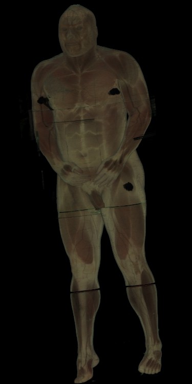
Figure 7: 1024x608x1878 cryosection dataset rendered in
11.8 seconds on 128 PEs.
7 Conclusion
Splatter is capable of rendering very large volume datasets on a
Cray T3D at interactive rates.
With a total of 8GB of RAM distributed over 128 PEs, the entire
Visible Male (at half resolution) can be rendered in under 12
seconds.
Since Splatter is scalable, smaller portions can be rendered
on smaller numbers of PEs in interactive times.
In addition, an AVS interface gives a user tremendous control over
exploring and creating animations of volume data sets that are too
large for workstations.
8 Future Work
Since the cryosection data is relatively new, further research needs
to be done on how to "shade" it.
While Splatter can generate multiple frames per second with
128^3 datasets, a parallel version of shear-warp transform [4]
or the fourier projection-slice [5] algorithm might be
necessary to get the same performance for larger datasets.
9 Acknowledgements
This research was supported by Cray Research Inc. and the National
Science Foundation.
We would also like to thank the National Library of Medicine for
providing the volume data from the Visible Human Project.
References
[1]
Mark Astley and Mitchell Roth.
Spline animator: Smooth camera motion for avs animation.
In Proceedings of the 1994 International AVS Users Conference,
pages 142-151, 1994.
[2]
Greg Johnson and Jon Genetti.
High resolution interactive volume rendering on the cray t3d.
In 1994 Fall Proceedings (Cray Users Group),
pages 119-125, 1994.
[3]
Greg Johnson and Jon Genetti.
Medical diagnosis using the cray t3d.
In 1995 Spring Proceedings (Cray Users Group)
pages 70-77, 1995.
[4]
Philippe Lacroute and Marc Levoy.
Fast volume rendering using a shear-warp factorization of the viewing
transformation.
In Andrew S. Glassner, editor, Computer Graphics (SIGGRAPH '94
Proceedings), pages 451-458, 1994.
[5]
Takashi Totsuka and Marc Levoy.
Frequency domain volume rendering.
In James T. Kajiya, editor, Computer Graphics (SIGGRAPH '93
Proceedings), volume 27, pages 271-278, August 1993.
[6]
Lee Westover.
Footprint evaluation for volume rendering.
In Forest Baskett, editor, Computer Graphics (SIGGRAPH '90
Proceedings), volume 24, pages 367-376, August 1990.