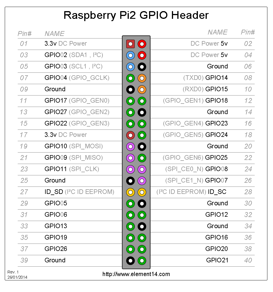
| GPIO Chip |
First GPIO Physical Address (in /dev/mem) |
|
| Raspberry Pi 1 |
BCM2835 |
0x20200000 |
| Raspberry Pi 2 |
BCM2836 | 0x3F200000 |
| Future Pis |
??? |
??? |
#include <stdio.h>    // for printf
#include <fcntl.h>    // for open
#include <sys/mman.h> // for mmap
#include <unistd.h>

long foo(void)
{
	int fdgpio=open("/dev/gpiomem",O_RDWR);
	if (fdgpio<0) { printf("Error opening /dev/gpiomem"); return -1; }

	unsigned int *gpio=(unsigned int *)mmap(0,4096,
		PROT_READ+PROT_WRITE, MAP_SHARED,
		fdgpio,0);
	printf("mmap'd gpiomem at pointer %p\n",gpio);

	// Read pin 8, by accessing bit 8 of GPLEV0
	return gpio[13]&(1<<8);
}
| Name |
Purpose |
Byte Offset |
Int Offset |
| GPLEV0 |
In input mode, each bit reads one GPIO pin. |
0x34 |
gpio[13] |
| GPSET0 |
In output mode, turn a GPIO pin high
by writing the corresponding bit here. E.g., GPIO pin 8 is bit 1<<8, so you set it with gpio[7]=1<<8; |
0x1C |
gpio[7] |
| GPCLR0 |
In output mode, turn a GPIO pin low
by writing the corresponding bit here. |
0x28 |
gpio[10] |
| GPFSEL0 |
Sets the mode for the first 10 I/O pins,
numbers 0..9. Each pin has a 3-bit field, with 000
meaning input, 001 meaning output, and 010 and higher
meaning "alternate functions" specific to each pin (see
chapter 6.2). |
0 |
gpio[0] |
| GPFSEL1 |
Sets the mode for the next 10 I/O pins,
numbers 10..19. |
4 |
gpio[1] |