2D Path Planning with Minkowski and OpenSCAD
CS
480: Robotics & 3D Printing Lecture, Dr. Lawlor
When doing path planning in 2D for a ground robot, we often work in
3D so we can explicitly represent the robot's orientation. The
Z axis units might be degrees, from 0 (robot facing forward) through
180 (robot facing backward) to 360 again (robot facing forward
again). This does mean the +Z and -Z faces wrap around.
Given a simple room shape, and a disk shaped robot, the
configuration space is very simple, with the walls inset by the
robot's radius. For a more complicated robot shape, the
allowable distance from the walls depends on the robot's
orientation, which makes the allowed region in configuration space
more complex.
It's possible to use OpenSCAD's minkowski sum to compute the allowed
region of the robot center in this 3D configuration space.
The rationale here is:
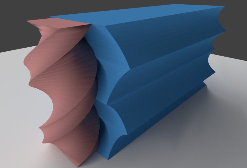
- We start with a 2D outline of the robot. Here we're
assuming a rectangular outline (actually the dimensions of our
NASA mining robot, 150cm x 75cm).
- We use a linear_extrude with a 360 degree helical twist to
explicitly represent the robot's shape at each orientation in
configuration space. This is shown in red below.
- We'd like to compute the region of configuration space where
the robot's center point can be, while keeping the robot from
touching any of the walls. This is shown in blue
below. The straight walls have become scalloped due the
robot's changing size in different orientations.
The OpenSCAD code is:
/**
  Robot 2D path planning in OpenSCAD

  Dr. Orion Lawlor, lawlor@alaska.edu, 2015-10-04 (Public Domain)
*/

// Number of orientations to check:
turn_slices=8; // every 45 degrees, under 1 minute
// turn_slices=36; // every 10 degrees, 3 minutes

// Robot 2D outline, mirrored on both axes
module robot_2D() {
    square(size=[150,75],center=true);
}

// Robot's 3D configuration space outline
module robot_3D() {
    linear_extrude(height=360,twist=-360,convexity=8,slices=turn_slices) robot_2D();
}

// Outline of room
module room_2D() {
    difference() {
        translate([-378/2,0,0])
            square(size=[378,738]);
        // projecting hole in room
        //translate([0,300])
        //    square(size=[500,200]);
    }
}

// Difference between environment and room
module room_disallowed() {
    difference() {
        translate([-300,-100,0])
            square(size=[600,1000]);
        room_2D();
    }
}

// Disallowed region for robot center point
module robot_disallowed() {
    minkowski() {
        robot_3D();
        linear_extrude(height=1)
            room_disallowed();
    }
}

// Allowed region for robot center point
module robot_allowed() {
    difference() {
        linear_extrude(height=360,convexity=2) room_2D();
        robot_disallowed();
    }
}


robot_3D();
robot_allowed();
(Download this OpenSCAD code)
One trick here is there isn't a built-in OpenSCAD operation to
compute "all center points of an object (the robot) while staying
inside the other object (the room)". So we compute this by
first computing the disallowed region outside the room, enlarging
this by the robot's size (the minkowski sum), and subtracting this
from the room's interior.
Minkowski runs quite slowly, taking nearly a minute even for a very
simple rectangular robot in a rectangular room under 8 different
orientations, but it is reliable and if you wait long enough, it
seems to work for arbitrary shaped robots in arbitrary shaped
rooms. For realtime robot use, you could precompute the
allowed region and export it as an STL or OBJ file.
This then converts checking a robot's intersection with the walls
with a much simpler point-in-STL test (e.g., Möller-Trumbore
ray/triangle test). I converted the ASCII STL file into
vertex() function calls with this UNIX command pipeline:
cat foo.stl | grep vertex | awk '{printf(" vertex(%.3f,%.3f,%.3f);\n",$2,$3,$4);}' > foo.js
Non-Holonomic Control
A control system is "holonomic" if the system's total number of
degrees of freedom equals the number of degrees of freedom we
can directly control. A system with 2D position and orientation has
three degrees of freedom. A system with two independently
controllable wheels (tank steering) has two degrees of freedom--it
can move forward or backward, and turn in place, but it cannot crab
sideways. By contrast, these omni wheels allow a
forklift to immediately move in any direction, or rotate in
place.
Non-holonomic control complicates navigation--even if we can spin in
place, moving directly along Z in configuration space, due to the
shape of the robot we may still hit a wall. We can drive
forward and backward, but only along our wheel direction.
(Related: Austin
Powers 3-point turn scene.)