Motor Types & Control Schemes

CS 480: Robotics & 3D Printing Lecture, Dr. Lawlor

An electric motor has a frame that does not rotate, called the stator because it is stationary; and a rotating center part called the rotor.  Nearly all electric motors work by using a coil of wire to create an electromagnet, that pushes against another magnetic field to drive the motor into motion.

2 Wires: Brushed DC Motor

A brushed DC motor passes the incoming electric current through a set of brushes to reach the rotor.  Typically the stator's magnetic field is a set of permanent magnets mounted to the frame.  As the rotor rotates, the brushes switch the rotor's magnetic poles to keep it perpendicular to the stator field, which gives the rotor continuous torque. 

To reverse the direction of rotation of a brushed DC motor, you simply apply a DC current of the opposite polarity. 

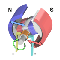
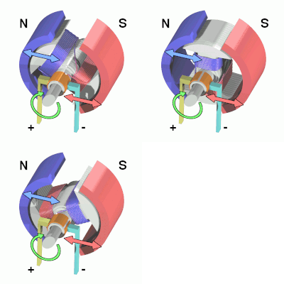
A simple DC electric motor. When the coil is powered, a magnetic field is generated by the rotor, causing rotation.
The rotor continues to rotate.
When the rotor becomes horizontally aligned, the torque becomes zero. At this point, the commutator reverses the direction of current through the coil, reversing the poles.

This "commutation" happens mechanically as the brushes rotate past the rotor.  Mechanical commutation is simple, but slowly wears away the copper commutator and graphite brushes, produces electrical arcing during opertion, and emits electrical and audible noise.  This electrical noise can cause interference in other parts of the system, especially sensitive sensing and control systems.

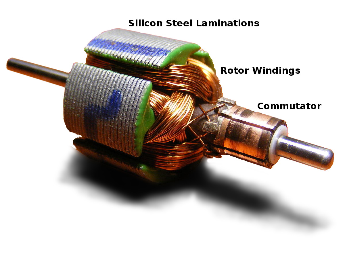
This is the rotor's mechanical appearance:
DC motor rotor, showing small copper commutator brushes,
        copper windings, and steel laminations
Many illustrations show a two-pole rotor, which is the simplest, but has two "dead zones" where the motor produces no torque, and also has a direct short across the commutator when the brushes are crossing between poles.  Real motors use a 3 or 5 pole rotor.

A DC motor's maximum torque is produced at low speed.  At higher speeds, less current flows through the rotor windings due to their inductance, reducing current consumed and torque produced.  Stall torque can be excellent, but without any inductance slowing the current through the windings, many DC brushed motors draw stall currents up to dozens of amps, and many will burn out within a few seconds when stalled due to resistive heating of their windings, even at their rated operating voltage.

If you apply an electric current, a DC motor produces torque.  If you want to control position, you need to add a position sensor, such as a potentiometer or magnetic encoder, and use this sensed value to achieve closed-loop control of position.  The combination of a DC motor, position sensor, and control electronics is known as a servo, which range from tiny servos for lightweight radio controlled aircraft, to heavy kilowatt-scale CNC servomotors.

Typical robotics applications:
Electrically, as the motor spins, the coil inductance keeps too much current from flowing through the windings.  But this means if a brushed DC motor stalls, it draws maximum power (and produces maximum torque) until it burns out its windings, which can happen in seconds if you're pushing a lot of voltage through a small motor. 

3 Wires: brushless three-phase motor

Unlike a brushed motor, a three-phase motor takes in alternating current directly on 3 wires, which feed stator coils to drive permanent magnets installed in the rotor.  The lack of brushes eliminates wear and a source of electrical noise, but it needs a more sophisticated external commutation circuit, which needs some way of measuring the rotor position to generate the right motor currents.  Above a few thousand RPM, it is possible to measure rotor position by watching for the zero-crossing voltage induced in the windings by the motion of the rotor; at lower RPMs it is more reliable to add a hall effect sensor to measure the rotor magnetic field directly.

Modern brushless motor controllers take the same R/C servo PWM signal as a servomotor.

Typical robotics applications:

4+ Wires: Stepper Motor

A stepper motor is a large pole count brushless motor.  Unlike three-phase motors, they are designed to allow reliable open-loop operation.

Typical robotics applications:

Hands-on with Real Motors

Jeremy Fielding gives a good tour of motor types, including AC induction motors with capacitor start, which are heavy reliable fixed-speed motors that are very common in appliances, but aren't used as much in robotics because you normally want variable speed, higher torque, and lower mass.