CPU and Instruction Set Design
CS 441/641 Lecture, Dr. Lawlor
CISC vs RISC vs VLIW
Back in the 1970's, when bits were expensive, the typical CPU encoding
used exactly as many bytes as each instruction needed and no
more. For example, a "return" instruction might use one byte
(0xc3), while a "load a 32-bit constant" instruction might use five
bytes (0xb8 <32-bit constant>). These
variable-sized instructions are (retroactively) called Complex
Instruction Set Computing (CISC), and x86 is basically the last surviving CISC machine.
During the 1980's, folks realized they could build simpler CPU decoders
if all the instructions took the same number of bytes, usually four
bytes. This idea is called Reduced Instruction Set Computing (RISC),
and was built into MIPS, PowerPC, SPARC, DEC Alpha, and other
commercial CPUs. Here's a good but long retrospective article on
the RISC-vs-CISC war, which got pretty intense during the 1990's. Nowadays, RISC machines might compress their instructions (like CISC), while CISC machines usually decode their instructions into fixed-size blocks (like RISC), so the war ended in the best possible way--both sides have basically joined forces!
During the late 1980's and early 1990's, several companies created even
longer instruction machines, called Very Long Instruction Word (VLIW),
where
basically each part of the CPU has corresponding bits in every
instruction. This makes for very simple decoding, and allows some
interesting parallel tricks, but each instruction might be a hundred
bytes or more! Modern graphics processors are typically VLIW
internally, and there are several strange digital signal processor
chips that are VLIW, but the concept hasn't really caught on for the
main CPU. And any company that produced a successful VLIW chip
would have a big problem building an improved processor, since each
instruction specifically describes what should happen on each part of
the old chip.
Assembly Basics
So here's some assembly language:
        Machine Code:           Assembly Code:
Address                    Instruction Operands
   0:	55                   	push   ebp
   1:	89 e5                	mov    ebp,esp
   3:	b8 07 00 00 00       	mov    eax,0x7
   8:	5d                   	pop    ebp
   9:	c3                   	ret
- Address. A byte
count, indicating where you are in a big list of bytes. The first
byte has address zero. An address can be thought of as an array
index into a big array of chars.
- Machine Code.
A set of bytes that the CPU can treat as instructions and execute. For
example, the byte "0xC3" tells the CPU to execute the instruction "ret"
(return from function). Human beings can write machine code (just wait for HW3!), but usually humans write Assembly Code instead.
- Assembly Code. The
human-readable counterpart to machine code. Assembly code is
line-oriented human readable text that lots of people write by
hand. You use an "assembler" to turn assembly code into
executable machine code. You can use a "disassembler" to turn
executable code into assembly code (try the NetRun "Disassemble"
checkbox for the code above!).
- Instruction. One command
for the CPU to execute. Can be thought of as: one line of
assembly code, or one set of machine code bytes. Depending on the
context, sometimes "instruction" includes the operands ("the 'push ebp'
instruction"), sometimes it doesn't ("the 'push' instruction, with
operand 'ebp'.").
- Operands. The
parameters taken by various instructions. These parameters can be
constants, like the "0x7" above, addresses in memory, or registers.
- Registers. Registers are little storage locations built into the CPU. They're used like variables in assembly language--you
spend most of your time putting values into registers, doing arithmetic
on register values, and moving values around between registers.
For example, "ebp", "esp", and "eax" above are all registers.
Unlike variables, there are a fixed number of registers (built into the
design of the CPU), and the registers have fixed names (built into the
assembler).
Here's a typical line of assembly code. It's one CPU instruction, with a comment:
mov eax,1234 ; I'm returning 1234, like the homework says...
(executable NetRun link)
Hardware Implementation
Each of the features of assembly language above corresponds to a
hardware circuit structure. I claim it's useful to know how these
work.
- You need to keep track of your address in the code, so there's a program counter.
- Instructions need to get loaded from somewhere (ROM or RAM), so there's an instruction fetch unit.
- Once you have an instruction, you need to figure out what operand and register's its talking about. This is done in the decode unit.
- Registers need to be stored, so there's a register file. You need a way to read and write them, so there are read and write ports.
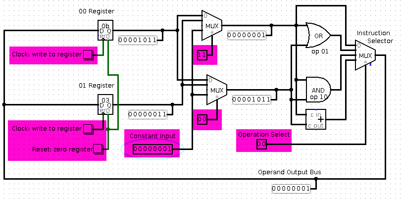
The simplest place to start is just to look at the registers and
arithmetic. We need control lines, highlighted in purple here, to
activate the different parts of the computation. Click this image
to get a runnable Logisim .circ file.
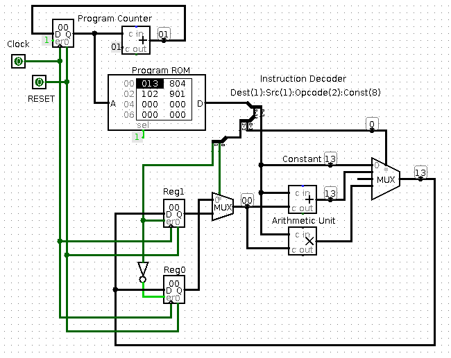
Here's the two-register, 12 bit instruction machine we designed in
class today. Conceptually, this is the same as above, except I'm
driving all the little control lines from a ROM; this stored program
dramatically simplifies the user interface.
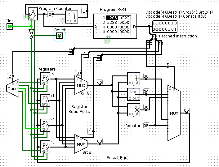
Here's a slightly more complex four register machine. The
instruction set is 16 bits per instruction, and is designed for future
compatibility for up to 16 registers. This is vaguely similar to
ARM.
Notice how:
- The wiring of the CPU is what *determines* the instruction set, so to change instruction sets, you need to use solder! Many machines have a look-up table called microcode that's used to decode instructions, which allows some flexibility to fix hardware bugs. Common instructions often bypass microcode via dedicated logic, for speed.
- If you're storing the instructions on-chip, weird instruction
lengths like 12 bits work fine. (For example, PIC
microcontrollers have 14-bit wide instructions). If the
instructions were coming from an off chip 8-bit or 16-bit RAM, this
size mismatch would be a problem.
- I've left out RAM access, branches, and error checking. These are all important in a real CPU.
Both CPUs above are RISC architectures, which makes the instruction
decoder very simple. In a CISC architecture, you need to keep
fetching instructions until you have one complete instruction.