Buses vs. Muxes, and Tri-State Logic
CS 441 Lecture, Dr. Lawlor
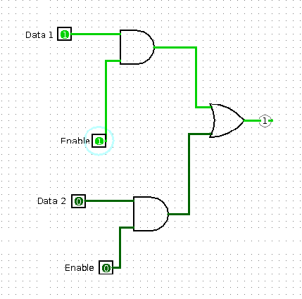
There are many places on a CPU where you need to choose one output of several possible inputs:
- The result of each operation can be driven by any arithmetic unit.
- Each output from the register file can be driven by any register.
The typical way to do this is using a multiplexer, or "mux", typically implemented using logic gates.
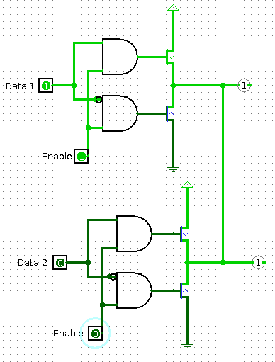
But there's another implementation using an analog circuit trick: you
can tie together several output lines, as long as you only enable a
single output line at a time. The big difference is that an
output device can enter a high-impedance "disconnected" state, leaving
to three modes: "on, off, or don't care", hence called tri-state logic.
These can be further simplified by noticing that the AND gates are only needed if the enable is true:
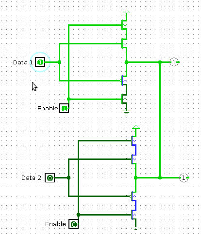
This tri-state solution only uses four transistors per output bit,
which is substantially fewer transistors than the mux approach (at
least 4 transistors per AND gate, plus the OR gate), and hence the
tri-state output bus solution is standard.
If you look at the 8008 microarchitecture, there's one big data bus running around the entire CPU.