Digital vs. Analog Circuits: Not a Binary Choice!
CS 441 Lecture, Dr. Lawlor
Counting on your fingers uses "digits" in the computational sense; digital storage uses discrete values, like the fingers which are either up or down. A 25%-raised pinky finger does not
represent one-quarter, it represents zero! This means your
fingers can bounce around a bit, and you can still tell which number
you're on. Lots of systems are digital:
- Counting on your fingers. (Individual fingers are either up or down.)
- Stop lights. (Lights are either green, yellow, or red.)
- The legal system. (You're either guilty or not guilty.)
- Computers. (It's either 1 or 0.)
- Digital radio (XM), digital audio, digital TV, digital cable (You either get a perfect noise-free signal, or you get nothing!)
The other major way to represent values is in analog.
Analog allows continuous variation, which initially sounds a lot better
than the jumpy lumpy digital approach. For example, you could
represent the total weight of sand in a pile by raising your pinky by
10% per pound. So 8.7 pounds of sand would just by an 87% raised
pinky. 8.6548 pounds of sand would be an 86.548% raised
pinky. Lots of systems are also analog:
- The real world under classical physics. (Weight, length,
pressure, sound, brightness, temperature, dirtyness, etc. all vary
continuously if you ignore quantum effects)
- Pre-2000 audio equipment. (Analog voltage represents sound pressure.)
- The telephone system. (It's an analog signal from your house to your telco.)
- FM and AM radio, analog TV, analog satellite. (All noisy analog broadcasts.)
Note that in theory, one pinky can represent weight with any desired degree of precision, but in practice,
there's no way to hold your pinky that steady, or to read off the
pinky-height that accurately. Sadly, it's not much easier to build a
precise electronic circuit than it is to build a more-precise pinky.
In other words, the problem with analog systems is that they are
precision-limited. To store a more precise weight, your storage
device must be made more precise. Precision stinks. The
real world is messy, and that messiness screws up electrical circuits
like it screws up everything else (ever hear of clogged pipes, fuel
injectors, or arteries?). Messiness includes noise and the gross
term "nonlinearity", which just means input-vs-output is not a
straight line--so the system's output isn't the same as its input.
Yes, it's always possible to make your system more
precise. The only problem is cost. For example, here's a
review of some excellent, shielded, quality AC power cables for audio equipment.
These cables supposedly pick up less noise than ordinary 50-cent AC
plug. But the price tag starts at $2500--for a 3-foot length!
Note in many cases the desired output is indeed highly nonlinear--the
output isn't simply proportional to the input. If you're
designing an analog audio amplification circuit, nonlinearity is
considered "bad", because it means
the output isn't a precise duplicate of the input, and the circuit has
lost signal quality (think of the rattling base thumping down the
street!). But most computations are nonlinear, so an analog
circuit to do those computations should also be nonlinear. Such analog computers,
without any digital logic, have actually been built! In some
sense, the best possible simulation of a mechanical system is the
system itself, which can be considered a mechanical analog computer
simulating... a mechanical analog computer. The downside of such
a "simulation" is noise, repeatability, and design and fabrication cost.
Luckily, digital systems can be made extraordinarily complex
without encountering noise problems. Digital systems scale better
because to gain precision in a digital system, you don't
have to make your digits better, you just add more digits. This
quantity-instead-of-quality approach seems to be the dominant way we
build hardware today. But be aware that analog computers might
make a comeback in a power-limited world--considering that a single
transistor can add, multiply, and divide, digital logic might not be
able to compete! Also, there are potential computability differences between digital and analog computers.
How many levels?
OK. So digital computation divides the analog world into discrete
levels, which gives you noise immunity, which lets you build more
capable hardware for less money. The question still remains: how many of these discrete levels should we choose to use?
- An analog system uses an infinite number of signal levels (a continuously varying signal)
- ATSC Digital TV uses 8 levels (see the "8vsb eye diagram")
- Gigabit ethernet uses 5 levels (PAM-5, -2v, -1v, 0v, +1v, +2v)
- Fast ethernet uses 3 levels (-1v, 0v, +1v)
- USB, serial, and digital logic almost all uses only two levels (0 and 1)
- A broken computer has only one level (off)
Two levels is the cheapest, crappiest system you can choose that will
still get something done. Hence, clearly, it will invariably be
the most popular!
For a visual example of this, here's a little TTL inverter-via-NAND circuit:
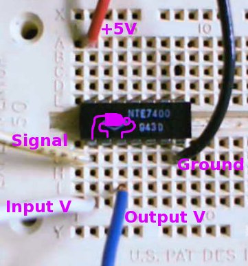
Here's the chip's input-vs-output voltage curve, measured using the "Input" and "Output" wires shown above.
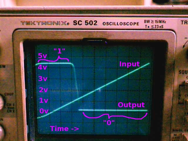
The Y axis is voltage, with zero thorough five volts shown. The X
axis is time, as the input voltage sweeps along. Two curves are
shown: the straight line is the input voltage, smoothly increasing from
slightly negative to close to 5 volts. The "output" curve is
high, over 4v for input voltages below 1v; then drops to near 0v output
for input voltages above 1.3v. High voltage is a "1"; low voltage
is a "0". So this circuit "inverts" a signal, flipping zero to
one and vice versa. Here's the digital input vs output for this
chip:
Here's the trace of another chip of the same type. Note the curve isn't exactly the same!
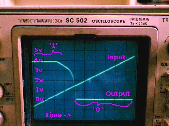
These two chips don't
behave in exactly the same way, at least seen from the analog
perspective of "how many volts is it sending out?". But seen from
the digital perspective, 0 or 1 output for 0 or 1 input, they're identical!