
Note that in the case of 1+1, a carry results into the next bit to the left.
In truth table form, the addition of two bits, a+b is:

Observe that a+b is identical to the logical xor operation and that carry is the same as the logical and operation.
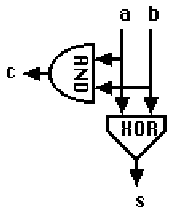
The operation of adding two bits to produce a sum and a carry is called a half adder. The logical operations in a half adder can be shown in the form of a logic diagram.

The half adder has two inputs, a and b, and two outputs, s and c, corresponding to the sum and carry bits.
Logic operations, such as and and xor, can be performed by simple electronic circuits using a high voltage to represent 1 and a low voltage for 0. This is the fundamental design principle for all digital computers.
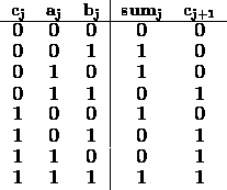
In order to perform addition on binary numbers, the carry bits must also be included in the sum. The truth table for full binary addition of the bits in position j is:

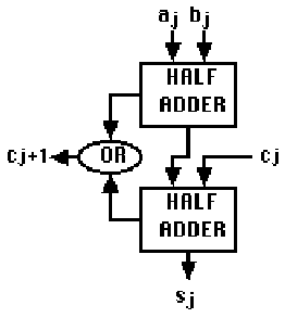
A full adder combines two half adders to add the carry bit from the previous bit position to the sum bit. A carry bit is produced by the full adder if either of the half adders produce a carry.

For bit j, the full adder has 3 inputs, ![]() ,
, ![]() , and
, and
![]() , and two outputs,
, and two outputs, ![]() and
and ![]() .
.
To add two binary numbers, the single bit addition operation is applied to all bits in the numbers. The binary addition algorithm for 32 bit integers can be implemented with logical operations in SAL as follows:
        .data
A:      .word             # the first number to be added
B:      .word             # the second number to be added
C:      .word             # used to hold carry bits
S:      .word             # the sum of A+B
T:      .word             # temp storage for partial sum
        .text
__start:
        xor     S, A, B   # form bitwise sums of A+B
        and     C, A, B   # form bitwise carrys of A+B
loop:   beqz    C, endadd # while (there are carrys)
        sll     C, C, 1   # shift the carry bits left
        move    T, S      # save partial sum
        xor     S, S, C   # add the carry bits to sum
        and     C, C, T   # form new carry bits
        b       loop      # end while
endadd:
In 2's complement representation, subtraction is performed by adding the additive inverse of a number. A number is negated by forming the complement and adding 1. Note that no tests are performed to detect addition overflow.
The binary addition algorithm requires as many as n iterations of the loop to add two n bit integers. Important logic operations, such as addition, are often implemented in high-speed logic circuits. Such circuits form the basis for machine instructions in the CPU.
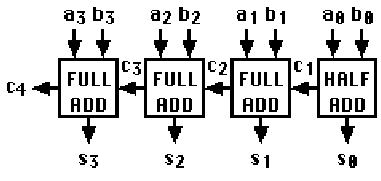
For example, a 4-bit addition circuit can be created from four full adders:

The time required for a logic circuit to produce a stable output voltage after the inputs are changed is called the propagation delay. Since each adder sends a carry bit to the left, the output of the leftmost adder depends on the outputs from all previous adders. The total time for a logic circuit to perform an n-bit addition operation is n times the propagation delay for one adder.
The propagation delay limits CPU clock speed because one clock cycle must be longer than the propagation delay. The propagation delay is determined by several factors, including the physical size, power, and material of logic circuits.