Building Simple CPUs
CS 641 Lecture, Dr. Lawlor
Silicon FET Transistors to Logic Gates
Modern transistors are FET transistors:
you charge up a small channel called the "gate", and it conducts
current between two terminals. In an "n-channel FET", the gate
already has plenty of electrons, so you need to discharge them with a
positive voltage to allow it to conduct. In a
"p-channel FET", you open the gate with a negative voltage. I
like Wikipedia's pictures for these: n-channel is a positive logic
input, and p-channel is an inverting input with an inverting circle.
You can build logic gates from FET transistors quite easily in a "totem pole" configuration. Here's an inverter:

When A is positive, it turns off the high gate, disconnecting Q from
positive voltage (Vdd); and turns on the low gate, connecting Q to the
negative voltage (Vss): A positive makes Q negative. When A is
negative, it turns on the high gate and off the low gate, connecting Q
to positive voltage and disconnecting negative voltage; A negative
makes Q positive.
Here's an AND gate built from FET transistors, and the corresponding silicon implementation:


It's surprisingly easy to build all the logic gates with FET transistors!
Logic Gates to Flip Flops
Once you've got logic gates, the next step is data storage. You can store data by chaining together logic gates in a flip-flops.
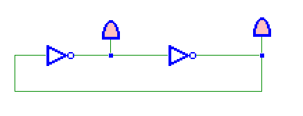
It's just a two inverters in series, looped back on the other one, so
it has two stable states: one inverter outputting true, or the other
outputting true.
Of course, it's handy to be able to write values into a flip flop, so a
"RS" (Reset and Set) flip-flop is made from NOR gates.
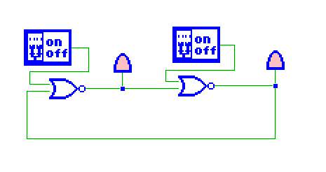
If both switches are off, the flip-flop just remembers its previous
value. If you turn on the left switch, "Reset", it makes the
middle wire go high and the right wire go low, storing a zero. If
you turn on the right switch, "Set", it makes the wrap-around wire go
low and the middle wire high, storing a one.
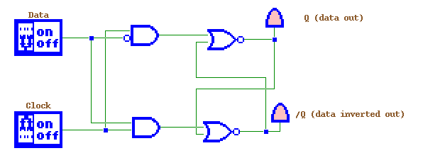
Often you want a "data" input, so you decode data and a write enable
line typically called "clock" to make the set and reset lines above:
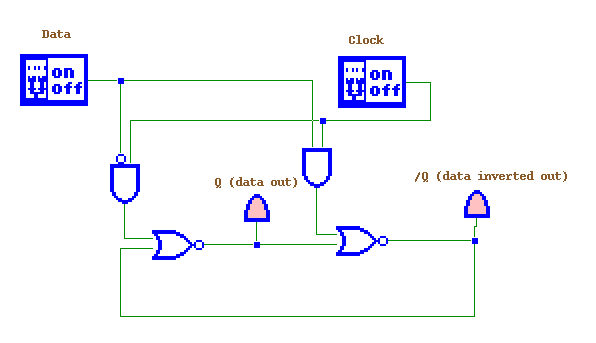
Flipflops are normally drawn with the two NOR gates' wires crossed,
which looks a little more symmetrical but substantially more confusing
(to me). This is the same circuit:
These flip-flops can be replicated one after another to store an
arbitrary number of bits. A collection of bits that can be read
or written together is a "register". A collection of registers is
called a "register file".
Logic and Registers into a CPU
First, a short survey of how to get work done in Logisim:
- To run the program, download the .jar file, and double-click it. Save often, because it can crash!
- Use the arrow tool to move parts around. Use the hand tool to push buttons and enter values.
- "Base -> Pin" is a very handy generic input. For data input, you probably don't want "three-state"": 0, 1, and x (don't care).
- "Base -> Probe" is a generic output. It automatically
sizes to match the wire you hook it to. Connect an Pin directly
to a Probe. Use the hand tool to poke at the pin, and the values
immediately change on the probe.
- "Gates -> AND Gate" is a scalable logic gate. Set the Gate Size to Narrow, and the Number O... to 2. Hook up two Pins to the input, and Probe to the output. Play with the gate.
- You can set the number of bits on the Pin and AND gate, such as 8
bits. It immediately scales the output Probe up to 8 bits.
You get an orange "Incompatible widths" error if input and outputs don't match up. Either change them to match, or use a Splitter or Bit Extender to address the mismatch.
- Try replacing the AND gate with an "Arithmetic ->
Adder". It's got optional carry-in and carry-out, but you can
leave them unconnected and it'll still work.
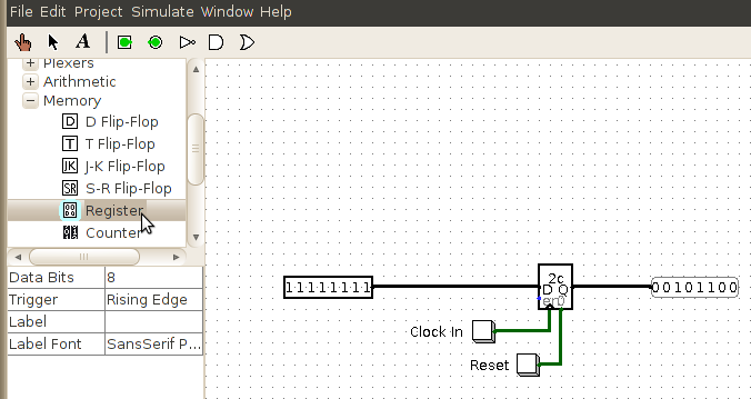
Here's a basic Register, which stores a value (displayed inside),
always outputs the value on the Q output, clears the value to zero with
the "0" input (bottom right side), and reads a new value from D when
you bring the "en" clock input high. I'm using an
"Input->Button" as a momentary input to clock in values, or reset
the value to zero. Click the image to get a Logisim .circ file to
play with.
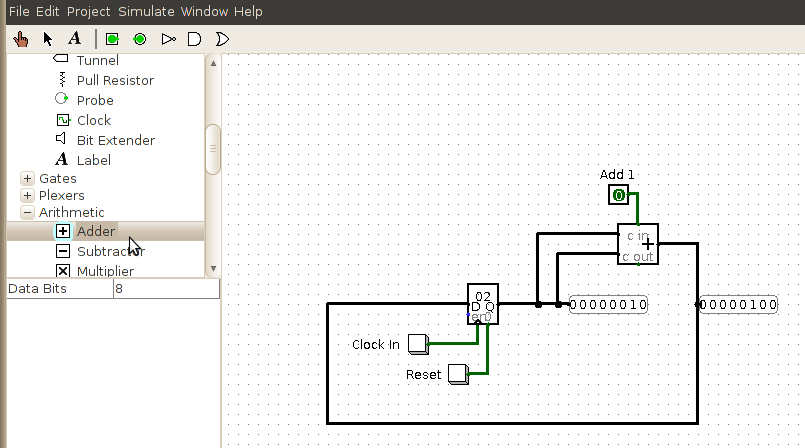
Here's the same register's output fed into an adder, which is then fed
back into the register's input again. This circuit just doubles
the value every time you hit "clock in".
Of course, a real CPU has lots of operations, not just addition.
But we can support different operations by multiplexing which operation
we want, using a "Plexers -> Multiplexer" or "mux". The mux's
input determines which operation we perform.
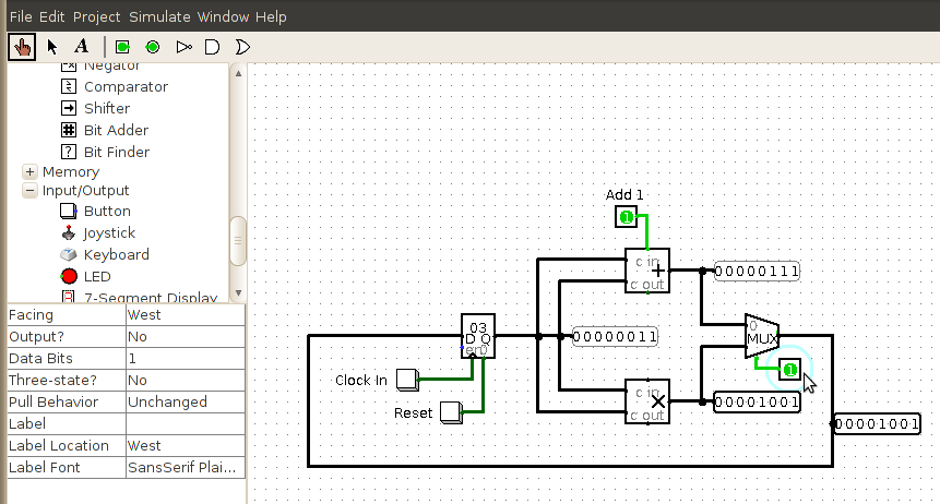
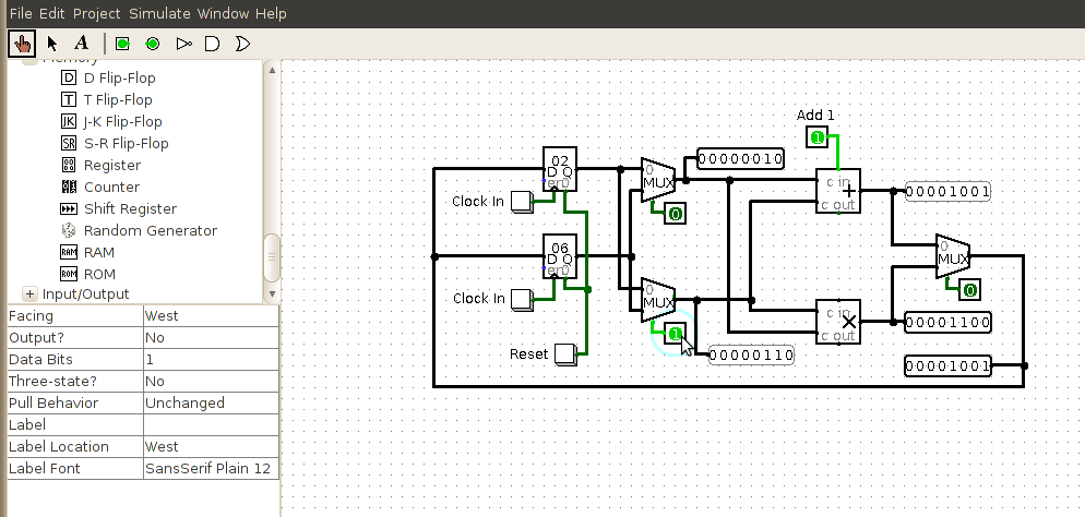
Finally, a real CPU can store more than one value at once. We can
choose which register to use as an input, by using a mux the same
way. We can now poke the various buttons, and get addition or
multiplication on any of the stored register values, store the value
back to any register, and operate back and forth indefinitely.
Given a list of button values, this circuit can compute stuff.
It's a CPU!